Showing posts with label Cisco R&S. Show all posts

Saturday, 5 March 2016

PRACTICE KNOCKS(CCNA)

Heya Guardians!!
Wassup... Enjoying the Holidays? Great..

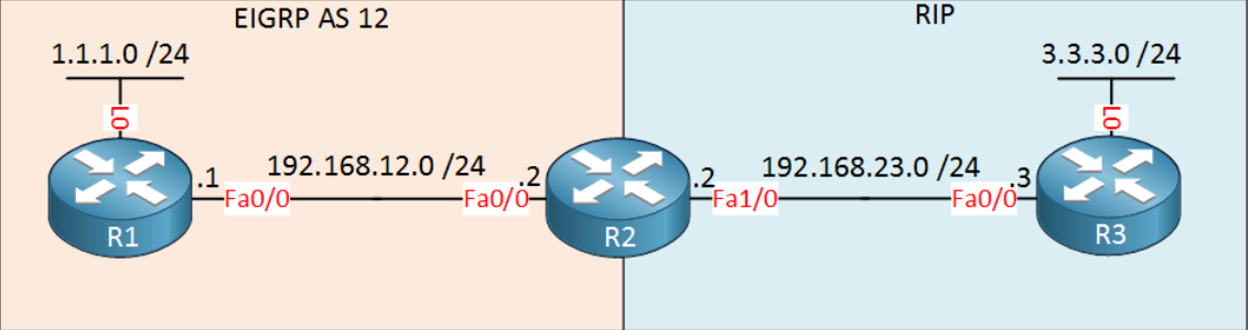
It's been a long time since we went through our blog. As we gonna start our further module CCNP let's revise our CCNA through some scenarios that covers some major topics. So let's do it (Me too ;-) ). Keep yourself thorough with every module covered in CCNA as

Many more are going to come! See you soon NetGuardians...


Sunday, 7 February 2016

Saturday, 30 January 2016

NETWORK PROTOCOLS (Defined)

TCP (Transmission Control Protocol)

Transmission Control Protocol uses a reliable delivery system to deliver layer 4 segments to the destination. This would be analogous to using a certified, priority, or next-day service with the Indian Speed Post;Service.
For example, with a certified letter, the receiver must sign for it, indicating the destination actually received the letter: proof of the delivery is provided. TCP operates under a similar premise: it can detect whether or not the destination received a sent segment. With the postal example, if the certified letter got lost, it would be up to you to resend it; with TCP, you don’t have to worry about what was or wasn’t received—TCP will take care of all the tracking and any necessary resending of lost data for you.
TCP’s main responsibility is to provide a reliable full-duplex, connection-oriented, logical service between two devices.
TCP goes through a three-way handshake to establish a session before data can be sent. Both the source and destination can simultaneously send data across the session. It uses windowing to implement flow control so that a source device doesn't overwhelm a destination with too many segments. It supports data recovery, where any missed or corrupted information can be re-sent by the source. Any packets that arrive out of order, because the segments traveled different paths to reach the destination, can easily be reordered, since segments use sequence numbers to keep track of the ordering.


UDP (User Datagram Protocol)

UDP uses a best-effort delivery system, similar to how first class and lower postal services of the Indian Postal Service work. With a first class letter (post card), you place the destination address and put it in your mailbox, and hope that it arrives at the destination.
With this type of service, nothing guarantees that the letter will actually arrive at the destination, but in most instances, it does. If, however, the letter doesn’t arrive at the destination, it’s up to you, the letter writer, to resend the letter: the post office isn’t going to perform this task for you.
UDP operates under the same premise: it does not guarantee the delivery of the transport layer segments. While TCP provides a reliable connection, UDP provides an unreliable connection.
UDP doesn’t go through a three-way handshake to set up a connection—it simply begins sending the data. Likewise, UDP doesn’t check to see whether sent segments were received by a destination; in other words, it doesn’t use an acknowledgment

Some commonly used ports

Port Number
Service
80
HTTP
21
FTP
110
POP3
25
SMTP
23
Telnet


FTP (File Transfer Protocol)

One of the earliest uses of the Internet, long before Web browsing came along, was transferring files between computers. The File Transfer Protocol (FTP) is used to connect to remote computers, list shared files, and either upload or download files between local and remote computers.
FTP runs over TCP, which provides a connection-oriented, guaranteed data-delivery service. FTP is a character-based command interface, although many FTP applications have graphical interfaces. FTP is still used for file transfer purposes, most commonly as a central FTP server with files available for download. Web browsers can make FTP requests to download programs from links selected on a Web page.
You should become familiar with the basic commands available in an FTP session. To begin a characterbased command session on a Windows computer, follow these steps.
  • Open a Command prompt window, type ftp at the prompt, and press Enter.
  • This will begin an FTP session on the local machine but will not initialize a connection to another machine.
  • Without a connection to another machine, you will not be able to do anything. To connect, type open example.com or open 10.10.10.1, in which exmple.com or 10.10.10.1 is the name or IP address of a host that is available as an FTP server. Most FTP servers require a logon id and password, or they will accept anonymous connections. At this point you will be prompted for a logon ID and password.
  • Once you are connected, you can list the files on the remote server by typing dir.
  • If you have create privileges on the remote server, you can create a new directory by typing mkdir.
  • To download a file, type get filename.txt where filename.txt is the name of the file you are downloading.
    To upload a file, type put filename.txt.


SFTP (Secure File Transfer Protocol)

SSH File Transfer Protocol or SFTP is a network protocol that provides file transfer and manipulation functionality over any reliable data stream.


TFTP (Trivial File Transfer Protocol)

TFTP is used when a file transfer does not require an acknowledgment packet during file transfer. TFTP is used often in router configuration. TFTP is similar in operation to FTP. TFTP is also a command-line-based utility.
One of the two primary differences between TFTP and FTP is speed and authentication. Because TFTP is used without acknowledgment packets, it is usually faster than FTP. TFTP does not provide user authentication like FTP and therefore the user must be logged on to the client and the files on the remote computer must be writable. TFTP supports only unidirectional data transfer (unlike FTP, which supports bi-directional transfer). TFTP is operated over port 69.


SMTP (Simple Mail Transfer Protocol)

SMTP is a standard electronic-mail protocol that handles the sending of mail from one SMTP to another SMTP server. To accomplish the transport, the SMTP server has its own MX (mail exchanger) record in the DNS database that corresponds to the domain for which it is configured to receive mail.
When equipped for two-way communication, mail clients are configured with the address of a POP3 server to receive mail and the address of an SMTP server to send mail. The clients can configure server parameters in the properties sheets of the mail client, basing the choices on an FQDN or an IP address.
SMTP uses TCP for communication and operates on port 25. Simple Mail Transfer Protocol (SMTP) is the application-layer protocol used for transmitting e-mail messages. SMTP is capable of receiving e-mail messages, but it's limited in its capabilities. The most common implementations of SMTP are in conjunction with either POP3 or IMAP4. For example, users download an e-mail message from a POP3 server, and then transmit messages via an SMTP server.


HTTP (Hypertext Transfer Protocol)

HTTP is often called the protocol of the Internet. HTTP received this designation because most Internet traffic is based on HTTP. When a user requests a Web resource, it is requested using HTTP. The following is a Web request:
http://www.example.com
When a client enters this address into a Web browser, DNS is called to resolve the Fully Qualified Domain Name (FQDN) to an IP address. When the address is resolved, an HTTP get request is sent to the Web server. The Web server responds with an HTTP send response. Such communication is done several times throughout a single session to a Web site. HTTP uses TCP for communication between clients and servers. HTTP operates on port 80.


HTTPS (Hypertext Transfer Protocol Secure)

HTTP is for Web sites using additional security features such as certificates. HTTPS is used when Web transactions are required to be secure. HTTPS uses a certificatebased technology such as VeriSign.
Certificate-based transactions offer a mutual authentication between the client and the server. Mutual authentication ensures the server of the client identity, and ensures the client of the server identity. HTTPS, in addition to using certificate-based authentication, encrypts all data packets sent during a session.
Because of the encryption, confidential user information cannot be compromised. To use HTTPS, a Web site must purchase a certificate from a third-party vendor such as VeriSign, CertCo, United States Postal Service, or other certificate providers. When the certificate is issued to a Web site from a third-party vendor, the Web site is using trusted communication with the client. The communication is trusted because the third party is not biased toward either the Web site or the client. To view a certificate during a HTTPS session, simply double-click the lock icon in the lower-right area of the Web browser. HTTPS operates on port 443 and uses TCP for communication.


POP3 / IMAP4 (Post Office Protocol version 3 / Internet Message Access Protocol version 4)

Post Office Protocol 3 (POP3) and Internet Message Access Protocol 4 (IMAP4) are two application-layer protocols used for electronic messaging across the Internet. POP3 is a protocol that involves both a server and a client. A POP3 server receives an e-mail message and holds it for the user. A POP3 client application periodically checks the mailbox on the server to download mail. POP3 does not allow a client to send mail, only to receive it. POP3 transfers e-mail messages over TCP port 110.
IMAP4 is an alternate e-mail protocol. IMAP4 works in the same way as POP3, in that an e-mail message is held on a server and then downloaded to an e-mail client application. Users can read their e-mail message locally in their e-mail client application, but they can't send an e-mail message using IMAP4. When users access e-mail messages via IMAP4, they have the option to view just the message header, including its title and the sender's name, before downloading the body of the message. Users can create, change, or delete folders on the server, as well as search for messages and delete them from the server.
To perform these functions, users must have continued access to the IMAP server while they are working with e-mail messages. With IMAP4, an e-mail message is copied from the server to the e-mail client. When a user deletes a message in the e-mail client, the message remains on the server until it is deleted on the server. POP3 works differently in that an e-mail message is downloaded and not maintained on the server, unless configured otherwise. Therefore, the difference between POP3 and IMAP4 is that IMAP4 acts like a remote file server, while POP3 acts in a store-and-forward manner in its default configuration. (You can configure POP3 clients to leave copies of messages on the server, if you prefer.)
Both Microsoft and Netscape Web browsers have incorporated POP3. In addition, the Eudora and Microsoft Outlook Express e-mail client applications support both POP3 and IMAP4.


Telnet

Short for Telecommunication Network, a virtual terminal protocol allowing a user logged on to one TCP/IP host to access other hosts on the network. Many people use remote control applications to access computers at their workplace from outside the network. In remote control, a session appears in which the user is able to manage the files on the remote computer, although the session appears to be functioning locally. Telnet is an early version of a remote control application.
Telnet is very basic; it offers solely character-based access to another computer. If you want to see a person's graphical desktop, you would need a different type of protocol, such as Remote Desktop Protocol (RDP), Independent Computing Architecture (ICA), or X Windows. Telnet acts as a user command with an underlying Transmission Control Protocol/Internet Protocol (TCP/IP) protocol that handles the establishment, maintenance, and termination of a remote session. The difference between using Telnet and a protocol such as File Transfer Protocol (FTP), is that Telnet logs you directly on to the remote host, and you see a window into that session on your local computer. A typical Telnet command might be as follows:
telnet example.com
Because this particular host is invalid, this command will have no result. However, if it were a valid host the remote computer would ask you to log on with a user ID and password. A correct ID and password would allow you to log on and execute Telnet commands.
You can often use Telnet to manage equipment that lacks a monitor. For example, most routers have Telnet enabled so that the administrator can log in and manage the router. Telnet also provides a quick check to make certain that network connectivity is functioning. Because Telnet sits at the application layer, if it can connect to a remote host, you can be certain that network connectivity between the two hosts is operational, as well as all lower-layer protocols.


SSH (Secure Shell)

SSH is a program for logging in to and executing commands on a remote machine. It provides secure encrypted communications between two untrusted hosts over an insecure network. X11 connections and arbitrary TCP/IP ports can also be forwarded over the secure channel. When SSH connects and logs in to a specified computer, the user must prove his/her identity to the remote machine which is transmitted across the connection using one of three forms of data encryption. This process makes SSH impervious to Internet eavesdroppers who might otherwise steal account information.


ICMP (Internet Control Message Protocol)

ICMP provides network diagnostic functions and error reporting. One of the most used IP commands is the Packet Internet Grouper (PING) command. When a host PINGS another client, it sends an ICMP ECHO request, and the receiving host responds with an ICMP ECHO REPLY. PING checks network connectivity on clients and routers. ICMP also provides a little network help for routers. When a router is being overloaded with route requests, the router sends a source quench message to all clients on the network, instructing them to slow their data requests to the router.


ARP / RARP (Address Resolution Protocol / Reverse Address Resolution Protocol)

The Address Resolution Protocol (ARP) is an Internet layer protocol that helps TCP/IP network components find other devices in the same broadcast domain. ARP uses a local broadcast (255.255.255.255) at layer 3 and FF:FF:FF:FF:FF:FF at layer 2 to discover neighboring devices. Basically stated, you have the IP address you want to reach, but you need a physical (MAC) address to send the frame to the destination at layer 2.
ARP resolves an IP address of a destination to the MAC address of the destination on the same data link layer medium, such as Ethernet. Remember that for two devices to talk to each other in Ethernet (as with most layer 2 technologies), the data link layer uses a physical address (MAC) to differentiate the machines on the segment. When Ethernet devices talk to each other at the data link layer, they need to know each other’s MAC addresses.
RARP is sort of the reverse of an ARP. In an ARP, the device knows the layer 3 address, but not the data link layer address. With a RARP, the device doesn’t have an IP address and wants to acquire one. The only address that this device has is a MAC address. Common protocols that use RARP are BOOTP and DHCP.

DHCP(Dynamic Host Control Protocol)

Dynamic Host Configuration Protocol (DHCP) is a client/server protocol that automatically provides an Internet Protocol (IP) host with its IP address and other related configuration information such as the subnet mask and default gateway. RFCs 2131 and 2132 define DHCP as an Internet Engineering Task Force (IETF) standard based on Bootstrap Protocol (BOOTP), a protocol with which DHCP shares many implementation details. DHCP allows hosts to obtain required TCP/IP configuration information from a DHCP server.


NTP (Network Time Protocol)

The Network Time Protocol is used to synchronize the time of a computer client or server to another server or reference time source, such as a radio or satellite receiver or modem. It provides accuracy's typically within a millisecond on LANs and up to a few tens of milliseconds on WANs.


SNMP

SNMP is a two-way network management protocol. SNMP consists of two components, the SNMP Agent, and the SNMP Management Console. The SNMP Management Console is the server side for SNMP. The management console sends requests to the SNMP Agents as get commands that call for information about the client.
The SNMP Agent responds to the Management Console’s get request with a trap message. The trap message has the requested information for the Management Console to evaluate. Security can be provided in many ways with SNMP; however, the most common form of security for SNMP is the use of community names, associations that link SNMP Agents to their Management Consoles:
  • Agents, by default, respond only to Management Consoles that are part of the same community name.
  • If an SNMP Agent receives a request from a Management Console that is not part of the same community name, then the request for information is denied.
Because SNMP is an industry-standard protocol, heterogeneous environments are common. Many vendors provide versions of SNMP Management Consoles. Hewlett Packard, for example provides HP Open View (one of the most popular Management Consoles on the market); Microsoft provides SNMP Server with the Windows NT and 2000 Resource Kits and Systems Management Server. SNMP Management Consoles request information according to a Management Information Base (MIB) format. An MIB is a numeric value that specifies the type of request, and to which layer of the OSI model the request is being sent.


SCP (Secure Copy Protocol)

Secure Copy or SCP is a means of securely transferring computer files between a local and a remote host or between two remote hosts, using the Secure Shell (SSH) protocol. The protocol itself does not provide authentication and security; it expects the underlying protocol, SSH, to secure this.
The SCP protocol implements file transfers only. It does so by connecting to the host using SSH and there executes an SCP server (scp). The SCP server program is typically the very same program as the SCP client.


LDAP (Lightweight Directory Access Protocol)

Lightweight Directory Access Protocol, or LDAP, is a networking protocol for querying and modifying directory services running over TCP/IP.
A directory is a set of information with similar attributes organized in a logical and hierarchical manner. The most common example is the telephone directory, which consists of a series of names organized alphabetically, with an address and phone number attached.
An LDAP directory often reflects various political, geographic, and/or organizational boundaries, depending on the model chosen. LDAP deployments today tend to use Domain Name System (DNS) names for structuring the topmost levels of the hierarchy. Deeper inside the directory might appear entries representing people, organizational units, printers, documents, groups of people or anything else which represents a given tree entry.


IGMP (Internet Group Multicast Protocol)

The Internet Group Management Protocol is a communications protocol used to manage the membership of Internet Protocol multicast groups. IGMP is used by IP hosts and adjacent multicast routers to establish multicast group memberships. It is an integral part of the IP multicast specification, like ICMP for unicast connections. IGMP can be used for online video and gaming, and allows more efficient use of resources when supporting these uses.


LPR (Line Printer Remote)

The Line Printer Daemon protocol/Line Printer Remote protocol (or LPD, LPR) also known as the Berkeley printing system, is a set of programs that provide printer spooling and network print server functionality for Unix-like systems.
The most common implementations of LPD are the official BSD UNIX operating system and the LPRng project. The Common Unix Printing System (or CUPS), which is more common on modern Linux distributions, borrows heavily from LPD.
A printer that supports LPD/LPR is sometimes referred to as a "TCP/IP printer" (TCP/IP is used to establish connections between printers and workstations on a network), although that term seems equally applicable to a printer that supports CUPS.

DHCP SERVER

Computers on a IP networks need some essentials information before it can communicate with other hosts. This information include an IP address, and a default route and routing prefix. Configuring IP addressing on a large TCP/IP-based network can be a nightmare, especially if machines are moved from one network to another frequently. DHCP eliminates the manual task by a network administrator. The Dynamic Host Configuration Protocol (DHCP) can help with the workload of configuring systems on a network by assigning addresses to systems on boot-up automatically. It also provides a central database of devices that are connected to the network and eliminates duplicate resource assignments.

DHCP server may have three methods of allocating IP-addresses:

Static allocation: The DHCP server allocates an IP address based on a table with MAC address/IP address pairs, which are manually filled Only requesting clients with a MAC address listed in this table will be allocated an IP address.
Dynamic allocation: A network administrator assigns a range of IP addresses to DHCP, and each client computer on the LAN is configured to request an IP address from the DHCP server during network initialization.
Automatic allocation: The DHCP server permanently assigns a free IP address to a requesting client from the range defined by the administrator. This is like dynamic allocation, but the DHCP server keeps a table of past IP address assignments, so that it can preferentially assign to a client the same IP address that the client previously had.
Among these three method static and dynamic method are the most popular implementation.

How DHCP work

DHCP provides an automated way to distribute and update IP addresses and other configuration information on a network. A DHCP server provides this information to a DHCP client through the exchange of a series of messages, known as the DHCP conversation or the DHCP transaction.


DHCP discovery

The client computers broadcasts messages on the physical subnet to discover available DHCP servers. This client-computers creates a User Datagram Protocol (UDP) packet with the default broadcast destination of 255.255.255.255 or the specific subnet broadcast address if any configured.

DHCP offer

When a DHCP server receives an IP lease request from a client, it reserves an IP address for the client and extends an IP lease offer by sending a DHCPOFFER message to the client. This message contains the client's MAC address, the IP address that the server is offering, the subnet mask, the lease duration, and the IP address of the DHCP server making the offer.

DHCP request

In most companies, two DHCP servers provide fault tolerance of IP addressing if one server fails or must be taken offline for maintenance. So client could receive DHCP offers from multiple servers, but it will accept only one DHCP offer. In response to the offer Client requests the server. The client replies DHCP Request, unicast to the server, requesting the offered address. Based on the Transaction ID field in the request, servers are informed whose offer the client has accepted. When other DHCP servers receive this message, they withdraw any offers that they might have made to the client and return the offered address to the pool of available addresses. In some cases DHCP request message is broadcast, instead of being unicast to a particular DHCP server, because the DHCP client has still not received an IP address. Also, this way one message can let all other DHCP servers know that another server will be supplying the IP address without missing any of the servers with a series of unicast messages.

DHCP acknowledgement

When the DHCP server receives the DHCPREQUEST message from the client, the configuration process enters its final phase. The acknowledgement phase involves sending a DHCPACK packet to the client. This packet includes the lease duration and any other configuration information that the client might have requested. At this point, the IP configuration process is completed.
                      

Differences Between FTP and TFTP

FTP, or File Transfer Protocol, and TFTP, or Trivial File Transfer Protocol, are both methods of file transfer over a network. That is where the similarities end, however. There are some very distinct differences that distinguish FTP from TFTP servers. Read on for a list of key differences.
Security
FTP is an encrypted file transfer system. This means that security measures such as password protection and encryption protect data as it is transferred. TFTP is not an encrypted file transfer system. For this reason, FTP is typically used by businesses.
Memory
When data is transferred between servers, a portion of the computer and server's memories are preoccupied during the transfer. Larger files and encrypted data take up more memory. TFTP is intended for the transfer of smaller files and does not require authentication. TFTP, therefore, requires less memory on a computer and server than FTP does.
Authentication
FTP requires authentication of a user's authority to upload and download files prior to releasing data resting on the server. Once the user is authenticated, the amount of data to which the user can have access is determined and is released simultaneously by FTP. TFTP, on the other hand, actually transfers data from the server directly to computers by breaking it down into manageable pieces that are then transferred sequentially from first to last between the server and a computer. If any piece fails to complete properly, the rest of the information is not sent.
Port Numbers
FTP utilizes TCP port connections. What this means is that it uses two different port numbers to establish two simultaneous connections. One port establishes authentication and controls the release of data based on the credentials of the user. The other port transfers data. TFTP utilizes UDP ports which make only a single connection between the server and user.
FTP is a more secure method of file sharing that makes it a more secure choice for businesses. TFTP is a better solution for those who only need to transfer a small amount of data without the need to protect it. When a request is made to access an FTP server, a session with a beginning and end is initiated. Accessing a TFTP server merely initiates the transfer of shared data.
Commands
Ftp - Robust Control Commands
Tftp - Simple Control Commands
Port no for FTP
20 for Data and 21 for Control
Port no for TFTP
69

Wednesday, 27 January 2016

TCP/IP protocols and architecture model diagram

Since TCP/IP is a protocol suite, it is most often discussed in terms of the protocols that comprise it. Each protocol “resides” in a particular layer of the TCP/IP architectural model we saw earlier in this section. Every TCP/IP protocol is charged with performing a certain subset of the total functionality required to implement a TCP/IP network or application. They work together to allow TCP/IP as a whole to operate.
First, a quick word on the word “protocol”. You will sometimes hear TCP/IP called just a “protocol” instead of a “protocol suite”. This is a simplification that while technically incorrect, is widely used. I believe it arises in large part due to Microsoft referring to protocol suites as “protocols” in their operating systems.
As I mentioned earlier in this section, there are a few TCP/IP protocols that are usually called the “core” of the suite, because they are responsible for its basic operation. Which protocols to include in this category is a matter of some conjecture, but most people would definitely include here the main protocols at the internet and transport layers: the Internet Protocol (IP), Transmission Control Protocol (TCP) and User Datagram Protocol (UDP). These core protocols support many other protocols, to perform a variety of functions at each of the TCP/IP model layers. Still others enable user applications to function.
On the whole, there are many hundreds of TCP/IP protocols and applications, and I could not begin to cover each and every one in this Guide. I do include sections discussing several dozen of the protocols that I consider important for one reason or another. Full coverage of each of these protocols (to varying levels of detail) can be found in the other chapters of this Guide.
Below I have included a number of tables that provide a summary of each of the TCP/IP protocols discussed in this Guide. Each table covers one of the TCP/IP model layers, in order from lowest to highest, and I have provided links to the sections or topics where each is discussed. The organization of protocols in the TCP/IP suite can also be seen at a glance in Figure


Wednesday, 20 January 2016

TCP/IP guide Vol 1 (check the link)

TCP/IP Guide Book
Happy networking!!

IPv4 introduction an its classes(brief)

Internet Protocol hierarchy contains several classes of IP Addresses to be used efficiently in various situations as per the requirement of hosts per network. Broadly, the IPv4 Addressing system is divided into five classes of IP Addresses. All the five classes are identified by the first octet of IP Address.
Internet Corporation for Assigned Names and Numbers is responsible for assigning IP addresses.
The first octet referred here is the left most of all. The octets numbered as follows depicting dotted decimal notation of IP Address:

The number of networks and the number of hosts per class can be derived by this formula:
 

When calculating hosts' IP addresses, 2 IP addresses are decreased because they cannot be assigned to hosts, i.e. the first IP of a network is network number and the last IP is reserved for Broadcast IP.

Class A Address

The first bit of the first octet is always set to 0 (zero). Thus the first octet ranges from 1 – 127, i.e.
 

Class A addresses only include IP starting from 1.x.x.x to 126.x.x.x only. The IP range 127.x.x.x is reserved for loopback IP addresses.
The default subnet mask for Class A IP address is 255.0.0.0 which implies that Class A addressing can have 126 networks (27-2) and 16777214 hosts (224-2).
Class A IP address format is thus: 0NNNNNNN.HHHHHHHH.HHHHHHHH.HHHHHHHH

Class B Address

An IP address which belongs to class B has the first two bits in the first octet set to 10, i.e.

Class B IP Addresses range from 128.0.x.x to 191.255.x.x. The default subnet mask for Class B is 255.255.x.x.
Class B has 16384 (214) Network addresses and 65534 (216-2) Host addresses.
Class B IP address format is: 10NNNNNN.NNNNNNNN.HHHHHHHH.HHHHHHHH

Class C Address

The first octet of Class C IP address has its first 3 bits set to 110, that is:

Class C IP addresses range from 192.0.0.x to 223.255.255.x. The default subnet mask for Class C is 255.255.255.x.
Class C gives 2097152 (221) Network addresses and 254 (28-2) Host addresses.
Class C IP address format is: 110NNNNN.NNNNNNNN.NNNNNNNN.HHHHHHHH

Class D Address

Very first four bits of the first octet in Class D IP addresses are set to 1110, giving a range of:

Class D has IP address rage from 224.0.0.0 to 239.255.255.255. Class D is reserved for Multicasting. In multicasting data is not destined for a particular host, that is why there is no need to extract host address from the IP address, and Class D does not have any subnet mask.

Class E Address

This IP Class is reserved for experimental purposes only for R&D or Study. IP addresses in this class ranges from 240.0.0.0 to 255.255.255.254. Like Class D, this class too is not equipped with any subnet mask.

ICMP (very important protocol of network layer) briefly explained

Even though IP is unreliable and doesn't guarantee delivery, it is important to notify the sender when something goes wrong. The Internet Control Message Protocol (ICMP) is the mechanism used to give feedback about network problems that are preventing packet delivery. Upper protocols, like TCP, will be able to realize that packets aren't getting through, but ICMP provides a method for discovering more catastrophic problems, such as "TTL exceeded" and "need more fragments." Infrequent problems, such as the IP checksum being wrong, will not be reported by ICMP. The premise is that TCP or other reliable protocols can deal with this type of packet corruption, and that if we're using an unreliable protocol like UDP, we shouldn't care about small amounts of loss.
Conversely, problems with the network will be reported immediately. For example, if the IP TTL is reaching zero, there's probably a routing loop somewhere and no packets are going to get through. The end system needs to know about these types of failures. ICMP is a protocol for sending various messages to report network conditions—it is not ping. The echo request is one of many messages. Ping can be filtered out, but the majority of ICMP message types are required for proper operation of IP, TCP and other protocols. Never let anyone tell you ICMP is evil and should be blocked.
ICMP itself is quite complex. Each type of ICMP message, called the "major type," also has "minor codes." ICMP lives just above Layer 3 (IP), so that it can be routed over the Internet. An ICMP packet is therefore an IP packet with ICMP in the IP data portion. Every ICMP message will also contain the entire IP header from the original message, so that the end system will know which packet actually failed. The first eight bytes of the original IP data will be included as well, and this is normally the TCP or UDP header.
In summary, the ICMP header contains three fields that never change, followed by the ICMP data, then the original IP header. The first 8 bytes contain the ICMP type (major type), the second contains the code (minor code), and the third field is a checksum of the ICMP message.
We need to realize that a few situations exist where ICMP will not send errors. ICMP errors will never be generated in response to an ICMP error message. If ICMP messages were sent in response to other ICMP messages, they would quickly multiply and create a storm of ICMP packets. ICMP messages will never be sent in response to a broadcast or multicast addresses either, to prevent broadcast storms.
The most useful ICMP packet is the Destination Unreachable messages, major type 3. Error messages are typically generated by routers, and sent to the original source of the packet. Most of the errors are also forwarded to the application concerned with the packet that was sent. In this vein, TCP makes extensive use of ICMP, as we'll see shortly.
A few of the most commonly used ICMP types in IPv4 include:
  • Echo Reply (0) and Echo Request (8): this is ping.
  • Destination Unreachable (3)
  • Source Quench (4): An ICMP message used to notify the sender that the router or host is congested, and the sender needs to slow down.
  • Redirect (5): a message used to say "use this other router instead" to a host that has access to both routers. We'll talk about this in detail in future routing issues of Networking 101.
  • Router Advertisement Reply (9) and Router Solicitation (10)
  • Time Exceeded (11): This message has two uses. First, it is used to send an error to the sending system when the IP TTL has been exceeded. Second, it will notify the sending system if a fragmented IP datagram isn't reassembled within a certain time limit.
And of course, there are minor codes within each of the above types. Type 3, destination unreachable, has 15 minor codes itself. We won't torture you with the details of everything, but there is one very important use of ICMP that relies on type 3 messages.
Path MTU (PMTU) discovery is the mechanism that protocols use to discover the largest supported MTU (maximum transmit unit) along the path, in hopes of avoiding fragmentation. The largest possible size is determined by the sender beginning with the MTU size of its local interface, and then simply shipping the data with the DF (don't fragment) bit set in the IP header. Everything will work as expected, or the sender will get back a type 3 ICMP error, with the code for "Fragmentation Required but the DF Flag is Set." When this happens, the sender knows that it must reduce the size of the data it is sending. If an error doesn't return, it assumes that the MTU is fine.
The main problem with PMTU discovery is that people block ICMP, preventing the error from reaching the sending host. Many times it takes place at the remote site you're trying to reach. Imagine that you're sending a request to a web server, but a blank page keeps loading. People on VPN connections see this effect more frequently, since their MTU is a bit smaller than the normal amount, due to extra headers for the VPN encapsulation. When the remote web server tries to send the VPN user the website it requested, the last router hop before the user will need to fragment the data, if it's too large. With the DF bit set, all it can do is notify the sender that it must send smaller packets, but the sender is blocking ICMP because it was deemed "evil" by policy makers. The website never loads. The good news is that most TCP implementations are a bit smarter. If they never get an ACK for the data sent, they should retransmit with a smaller segment size, but this doesn't always happen with certain popular, easy-to-use operating systems.
In short, blocking ICMP is detrimental to the successful operation of networks. It will break more than just ping; in fact, many protocols will be neutered if ICMP isn't working.

Saturday, 16 January 2016

TCP/IP explained (little better than before)

TCP/IP Model – 5 Layers

TCP/IP (Transmission Control Protocol/Internet Protocol) is the basic communication language or protocol of the Internet. It can also be used as a communications protocol in a private network (either an intranet or an extranet). When you are set up with direct access to the Internet, your computer is provided with a copy of the TCP/IP program just as every other computer that you may send messages to or get information from also has a copy of TCP/IP 

Application Layer (5)
watermarked-AppLayer
The TCP/IP Application Layer protocols provide services to the application software running on a PC or Server such HTTP, FTP, SMTP, POP3, and much more. The application layer does not define the application itself, but it defines services that applications need. E.g. application HTTP defines how web browsers can pull the contents of a web page from a web server. Therefore, the application layer provides an interface between a browser running on a PC and a web services running on a web server.
Representation Overview as Part of App Layer: The TCP/IP Representation Layer part of the Operating System level where it converts incoming and outgoing data stream to represent it in a specific file format using a specific window such text, jpeg, and html window with the help of its appropriate program. In addition, data encryption happens at this layer as well since that’s where it can be represented.
Notice: that the Presentation Layer at TCP/IP Model is a feature included with Application Layer.
Session Overview as Part of App Layer: The TCP/IP Session Layer can be considered the manager of session between the PC and a remote PC or Server from setting up, coordinate, terminate, exchange, and manage the application sessions from starting point to the end point.
Notice: that the Session Layer at TCP/IP Model is a feature included with Application Layer.
Transport Layer (4)
watermarked-Trans-layer
Here where the Data get Segmented based on TCP or UDP Port numbers and IP Addresses, together “IP-Address:Port”  called ” TCP Socket or UDP Socket”. The Transport Layer uses the two most common protocols Transmission Control Protocol (TCP) and the User Datagram Protocol (UDP) for Segmenting. This article will mention little bit about TCP Error Recovery. Check Understanding TCP and UDP Protocols Article for More Information.
TCP Error Recovery Overview: uses the concept of Acknowledgments and to appreciate what the TCP does, you must think about the layers above the Transport Layer, starting from Application Layer. Technically, each layer in TCP/IP provides a service to the layer above it, like TCP Error-Recovery service provided especially for Application layer. TCP mechanism guarantee delivery of data across the Network. Therefore, many Application Layer protocols such HTTP requires guarantee data delivery across a network, hence, TCP port 80 is used to recover data segments due to corrupted frames on the way.
Network Layer (3)
watermarked-Net-layer
Here where the segments get Packet. Network Layers includes major protocols. Most commonly used: Internet Protocol (IP). IP manage several services like IP Addressing, and IP Routing. This article compares IP Addressing and IP Routing logic concepts with another commonly known concept that uses Addressing and Routing: Postal Service.
Data-Link Layer (2)
watermarked-Data-link-layer
Here where IP Packets get Framed, and here where the last piece of Software control protocol can be applied on the Data before it can be handled as frame to the Hardware Layer (Physical Layer) for bit transmission. Since Data Link Layer has to deal with different media technology, it includes more standards and protocols than Network Layer. For example, it includes all the variations of Ethernet protocols, along with several other LAN and Wan Technologies. Wide Area Network (WAN) protocol standards which differ significantly compared to Ethernet Standards because of the longer distance involved in transmitting the Data, hence, different type of cable technology used with WAN.
Such WAN Control Protocols are: Point-to-Point (PPP), High-Level Data-Link Control (HDLC), and WAN’s Frame Relay Control Protocols and standards, just to name a few. So in short, Data Link Layer defines the functions used in these Protocols such rules and controls to deliver the IP Packets that hold the data through different types of Physical media.
Physical Layer (1)
watermarked-physical-layer
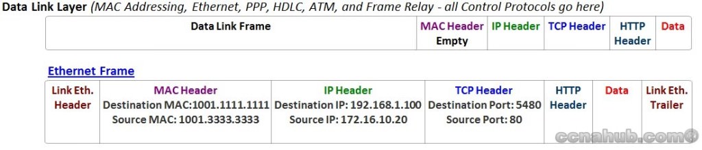
At this stage of the communication process and based on the figures above, the data has been segmented by the Transport Layer using destination and source TCP Port Numbers, placed into an IP packet by Network Layer using a destination and source IP addresses, encapsulated as Ethernet Header and Trailer forming a frame, with destination and source MAC addresses. Next: Physical Layer on the Downstream and based on the media used, creates an electrical, optical, or radiowave signals that represents the bits in each frame. These signals are then sent on the media one at a time. It is also the job of the Physical Layer to retrieve these individual signals from the media, restore them to their bit representations, and pass the bits up to the Data Link Layer as a complete frame.

Networking Basic

  • Repeater and Hub are layer 1 devices. Repeater address the issue of attenuation. Attenuation is the loss of signal over distance. Repeater rebuilt the electrical signal that comes in and send it out to other side. Hub is a multi-port repeater. Electrical signal came into any one hub port will be repeated on all other ports.The layer 1 devices are dumb, they have no decision making abilities. Hubs do not read any of the data passing through them, and they are not aware of the source or destination of the frame. All the devices attached to a hub are belong to one collision domain, which means if two hosts try to send data at the same time, a collision will occur. All the devices attached to a hub are also belong to one braoadcast domain, that is, broadcast frame sent by one host will be received by all other hosts in the network.
  • Bridge and Switch are layer 2 devices. They can make decisions about to which port the frames will go, based on MAC Addresses. Bridges and switches help avoid frame collision by breaking down one collision domain to two or more smaller collision domains, then buffer and forward frames between them. Nowadays, a switch can be configured to allow each connected host to have its own individual collision domain. As a result, all the hosts can trasnmit data simultaneously without collision, because they no longer share the bandwidth with each other. It is important to notice hosts attached to bridge or switch still belong to the same broadcast domain.
  • Router is layer 3 device. The purpose of router is to route packets from one broadcast domain to another. Router maintains a routing table. The routing table contains ip addresses associated with interfaces, out of which the packet will be forward to.
Collision Domains – A collision domain is defined as a network segment that shares bandwidth with all other devices on the same network segment. Generally speaking, A Collision Domain includes all of the Ethernet segments between a pair of bridges or other layer 2 devices. When two hosts on the same network segment transmit at the same time, the resulting digital signals will fragment or collide, hence the term collision domain.
Broadcast Domain – A broadcast domain is defined as all devices on a network segment that hear broadcasts sent on that segment.
All devices plugged into a hub are in the same collision domain and the same broadcast domain.
All devices plugged into a switch are in separate collision domains but the same broadcast domain. Although, you can buy special hardware to break up broadcast domains in a switch, or use a switch capable of creating VLANs. VLANs breakup broadcast domains.
Hubs and Repeaters extend collision and broadcast domains.
SwitchesBridges and Routers break up collision domains.
Routers (and Switches using VLANs) break up broadcast domains.
Bridging vs. LAN Switching
Layer 2 switches are just bridges with a lot more ports, more advanced functionality, and higher speed. They both forward layer 2 broadcasts, learn MAC addresses by examining the source address of each frame received and make forwarding decisions based on layer 2 addresses.
There are some important differences between bridge and LAN switch:
  • Bridges are software based, while switches are hardware based because they use ASIC chips to help make filtering decisions.
  • There can be only one spanning-tree instance per bridge, while switches can have many.
  • Switches have a higher port density than most bridges.
  • Switches have larger frame buffers.
  • Switches support for mixed media rates.
  • Switches support dedicated communication between devices.
  • Switch ports can run in full-duplex mode. In full-duplex mode the collision counter is inactive. If FCS, CRC errors increment then the most likely cause is a duplex mismatch. Other causes can be a faulty cable, a faulty switch port or hardware/software issues with NIC.

ETHERNET NETWORKING

Ethernet is a contention media access method that allows all hosts on a network to share the same bandwidth of a link. Ethernet is popular because it's readily scalable, meaning that it's comparatively easy to integrate new technologies, such as Fast Ethernet and Gigabit Ethernet, into an existing network infrastructure. It's also relatively simple to implement in the first place, and with it, troubleshooting is reasonably straightforward.
Ethernet networking uses Carrier Sense Multiple Access with Collision Detection (CSMA/CD), a protocol that helps devices share the bandwidth evenly without having two devices transmit at the same time on the network medium. CSMA/CD was created to overcome the problem of those collisions that occur when packets are transmitted simultaneously from different nodes.
When a host wants to transmit over the network, it first checks for the presence of a digital signal on the wire. If all is clear (no other host is transmitting), the host will then proceed with its transmission. The transmitting host constantly monitors the wire to make sure no other hosts begin transmitting. If the host detects another signal on the wire, it sends out an extended jam signal that causes all nodes on the segment to stop sending data (like a phone busy signal). The nodes respond to that jam signal by waiting a while before attempting to transmit again. Backoff algorithms determine when the colliding stations can retransmit. If collisions keep occurring after 15 tries, the nodes attempting to transmit will then time out.

Half- and Full-Duplex Ethernet

Half-duplex Ethernet is defined in the original 802.3 Ethernet; Cisco says it uses only one wire pair with a digital signal running in both directions on the wire. Certainly, the IEEE specifications discuss the process of half duplex somewhat differently, but what Cisco is talking about is a general sense of what is happening here with Ethernet.
It also uses the CSMA/CD protocol to help prevent collisions and to permit retransmitting if a collision does occur. If a hub is attached to a switch, it must operate in half-duplex mode because the end stations must be able to detect collisions. Half-duplex Ethernet - typically 10BaseT - is only about 30 to 40 percent efficient as Cisco sees it, because a large 10BaseT network will usually only give you 3 to 4Mbps - at most. But full-duplex Ethernet uses two pairs of wires, instead of one wire pair like half duplex and full duplex uses a point-to-point connection between the transmitter of the transmitting device and the receiver of the receiving device. This means that with full-duplex data transfer, you get a faster data transfer compared to half duplex. And because the transmitted data is sent on a different set of wires than the received data, no collisions will occur. Imagine a freeway with multiple lanes instead of the single-lane road provided by half duplex. Full-duplex Ethernet is supposed to offer 100 percent efficiency in both directions - e.g., you can get 20Mbps with a 10Mbps Ethernet running full duplex, or 200Mbps for Fast Ethernet. But this rate is something known as an aggregate rate, which translates as "You're supposed to get" 100 percent efficiency.
Full-duplex Ethernet can be used in three situations:
  • With a connection from a switch to a host
  • With a connection from a switch to a switch
  • With a connection from a host to a host using a crossover cable


Ethernet at the Data Link Layer

Ethernet at the Data Link layer is responsible for Ethernet addressing, commonly referred to as hardware addressing or MAC addressing. Ethernet is also responsible for framing packets received from the Network layer and preparing them for transmission on the local network through the Ethernet contention media access method. There are four different types of Ethernet frames available:
  • Ethernet_II
  • IEEE 802.3
  • IEEE 802.2
  • SNAP

Ethernet addressing uses the Media Access Control:

(MAC) address burned into each and every Ethernet Network Interface Card (NIC). The MAC, or hardware address, is a 48-bit (6-byte) address written in a hexadecimal format. Here is the 48-bit MAC addresses and how the bits are divided.


The organizationally unique identifier (OUI) is assigned by the IEEE to an organization. It's composed of 24 bits, or 3 bytes. The organization, in turn, assigns a globally administered address (24 bits, or 3 bytes) that is unique to each and every adapter they manufacture. Look at the figure and you will see that the high-order bit is the Individual/Group (I/G) bit. When it has a value of 0, we can assume that the address is the MAC address of a device and may well appear in the source portion of the MAC header. When it is a 1, we can assume that the address represents either a broadcast or multicast address in Ethernet, or a broadcast or functional address in TR and FDDI. The next bit is the G/L bit (also known as U/L, where U means universal). When set to 0, this bit represents a globally administered address (as by the IEEE). When the bit is a 1, it represents a locally governed and administered address (as in DECnet). The low-order 24 bits of an Ethernet address represent a locally administered or manufacturer-assigned code. This portion commonly starts with 24 0s for the first card made and continues in order until there are 24 1s for the last (16,777,216th) card made.


Ethernet Frames

The Data Link layer is responsible for combining bits into bytes and bytes into frames. Frames are used at the Data Link layer to encapsulate packets handed down from the Network layer for transmission on a type of media access. There are three types of media access methods: contention (Ethernet), token passing (Token Ring and FDDI), and polling (IBM mainframes and 100VG-AnyLAN). The function of Ethernet stations is to pass data frames between each other using a group of bits known as a MAC frame format. This provides error detection from a cyclic redundancy check (CRC). But remember - this is error detection, not error correction! The 802.3 frames and Ethernet frame are shown in the following figure
                           

802.2 and SNAP

Since the 802.3 Ethernet frame cannot by itself identify the upper-layer (Network) protocol, it obviously needs some help. The IEEE defined the 802.2 LLC specifications to provide this function and more. Below is shown the IEEE 802.3 with LLC (802.2) and the Subnetwork Access Protocol (SNAP) frame types.


Ethernet at the Physical Layer

Ethernet was first implemented by a group called DIX (Digital, Intel, and Xerox). They created and implemented the first Ethernet LAN specification, which the IEEE used to create the IEEE 802.3 Committee. This was a 10Mbps network that ran on coax, and then eventually twistedpair and fiber physical media. The IEEE extended the 802.3 Committee to two new committees known as 802.3u (Fast Ethernet) and 802.3ab (Gigabit Ethernet on category 5) and then finally 802.3ae (10Gbps over fiber and coax).
The EIA/TIA (Electronic Industries Association and the newer Telecommunications Industry Alliance) is the standards body that creates the Physical layer specifications for Ethernet. The EIA/TIA specifies that Ethernet uses a registered jack (RJ) connector with a 4 5 wiring sequence on unshielded twisted-pair (UTP) cabling (RJ-45). However, the industry is moving toward calling this just an 8-pin modular connector.
Each Ethernet cable type that is specified by the EIA/TIA has inherent attenuation, which is defined as the loss of signal strength as it travels the length of a cable and is measured in decibels (dB). The cabling used in corporate and home markets is measured in categories. A higher quality cable will have a higher rated category and lower attenuation.
Here are the original IEEE 802.3 standards:
  • 10Base2 10Mbps, baseband technology, up to 185 meters in length. Known as thinnet and can support up to 30 workstations on a single segment. Uses a physical and logical bus with AUI connectors. The 10 means 10Mbps, Base means baseband technology, and the 2 means almost 200 meters. 10Base2 Ethernet cards use BNC (British Naval Connector, Bayonet Neill Concelman, or Bayonet Nut Connector) and T-connectors to connect to a network.
  • 10Base5 10Mbps, baseband technology, up to 500 meters in length. Known as thicknet. Uses a physical and logical bus with AUI connectors. Up to 2500 meters with repeaters and 1024 users for all segments.
  • 10BaseT 10Mbps using category 3 UTP wiring. Unlike the 10Base2 and 10Base5 networks, each device must connect into a hub or switch, and you can only have one host per segment or wire. Uses an RJ-45 connector (8-pin modular connector) with a physical star topology and a logical bus.
Here are the expanded IEEE Ethernet 802.3 standards:
  • 100BaseTX (IEEE 802.3u) EIA/TIA category 5, 6, or 7 UTP two-pair wiring. One user per segment; up to 100 meters long. It uses an RJ-45 connector with a physical star topology and a logical bus.
  • 100BaseFX (IEEE 802.3u) Uses fiber cabling 62.5/125-micron multimode fiber. Point-topoint topology; up to 412 meters long. It uses an ST or SC connector, which are media-interface connectors.
  • 1000BaseCX (IEEE 802.3z) Copper twisted-pair called twinax (a balanced coaxial pair) that can only run up to 25 meters.
  • 1000BaseT (IEEE 802.3ab) Category 5, four-pair UTP wiring up to 100 meters long.
  • 1000BaseSX (IEEE 802.3z) MMF using 62.5- and 50-micron core; uses a 850 nanometer laser and can go up to 220 meters with 62.5-micron, 550 meters with 50-micron.
  • 1000BaseLX (IEE 802.3z) Single-mode fiber that uses a 9-micron core and 1300 nanometer laser, and can go from 3 kilometers up to 10 kilometers.

Friday, 15 January 2016

TCP Header Format

TCP Header Format


TCP segments are sent as internet datagrams. The Internet Protocol header carries several information fields, including the source and destination host addresses [2]. A TCP header follows the internet header, supplying information specific to the TCP protocol. This division allows for the existence of host level protocols other than TCP.
TCP Header Format
                                    
    0                   1                   2                   3   
    0 1 2 3 4 5 6 7 8 9 0 1 2 3 4 5 6 7 8 9 0 1 2 3 4 5 6 7 8 9 0 1 
   +-+-+-+-+-+-+-+-+-+-+-+-+-+-+-+-+-+-+-+-+-+-+-+-+-+-+-+-+-+-+-+-+
   |          Source Port          |       Destination Port        |
   +-+-+-+-+-+-+-+-+-+-+-+-+-+-+-+-+-+-+-+-+-+-+-+-+-+-+-+-+-+-+-+-+
   |                        Sequence Number                        |
   +-+-+-+-+-+-+-+-+-+-+-+-+-+-+-+-+-+-+-+-+-+-+-+-+-+-+-+-+-+-+-+-+
   |                    Acknowledgment Number                      |
   +-+-+-+-+-+-+-+-+-+-+-+-+-+-+-+-+-+-+-+-+-+-+-+-+-+-+-+-+-+-+-+-+
   |  Data |           |U|A|P|R|S|F|                               |
   | Offset| Reserved  |R|C|S|S|Y|I|            Window             |
   |       |           |G|K|H|T|N|N|                               |
   +-+-+-+-+-+-+-+-+-+-+-+-+-+-+-+-+-+-+-+-+-+-+-+-+-+-+-+-+-+-+-+-+
   |           Checksum            |         Urgent Pointer        |
   +-+-+-+-+-+-+-+-+-+-+-+-+-+-+-+-+-+-+-+-+-+-+-+-+-+-+-+-+-+-+-+-+
   |                    Options                    |    Padding    |
   +-+-+-+-+-+-+-+-+-+-+-+-+-+-+-+-+-+-+-+-+-+-+-+-+-+-+-+-+-+-+-+-+
   |                             data                              |
   +-+-+-+-+-+-+-+-+-+-+-+-+-+-+-+-+-+-+-+-+-+-+-+-+-+-+-+-+-+-+-+-+

                            TCP Header Format

          Note that one tick mark represents one bit position.

                               Figure 3.
Source Port: 16 bits
    The source port number.
Destination Port: 16 bits
    The destination port number.
Sequence Number: 32 bits
    The sequence number of the first data octet in this segment (except
    when SYN is present). If SYN is present the sequence number is the
    initial sequence number (ISN) and the first data octet is ISN+1.
Acknowledgment Number: 32 bits
    If the ACK control bit is set this field contains the value of the
    next sequence number the sender of the segment is expecting to
    receive.  Once a connection is established this is always sent.
Data Offset: 4 bits
    The number of 32 bit words in the TCP Header.  This indicates where
    the data begins.  The TCP header (even one including options) is an
    integral number of 32 bits long.
Reserved: 6 bits
    Reserved for future use.  Must be zero.
Control Bits: 6 bits (from left to right):
    URG:  Urgent Pointer field significant
    ACK:  Acknowledgment field significant
    PSH:  Push Function
    RST:  Reset the connection
    SYN:  Synchronize sequence numbers
    FIN:  No more data from sender
Window: 16 bits
    The number of data octets beginning with the one indicated in the
    acknowledgment field which the sender of this segment is willing to
    accept.
Checksum: 16 bits
    The checksum field is the 16 bit one's complement of the one's
    complement sum of all 16 bit words in the header and text.  If a
    segment contains an odd number of header and text octets to be
    checksummed, the last octet is padded on the right with zeros to
    form a 16 bit word for checksum purposes.  The pad is not
    transmitted as part of the segment.  While computing the checksum,
    the checksum field itself is replaced with zeros.

    The checksum also covers a 96 bit pseudo header conceptually
    prefixed to the TCP header.  This pseudo header contains the Source
    Address, the Destination Address, the Protocol, and TCP length.
    This gives the TCP protection against misrouted segments.  This
    information is carried in the Internet Protocol and is transferred
    across the TCP/Network interface in the arguments or results of
    calls by the TCP on the IP.

                     +--------+--------+--------+--------+
                     |           Source Address          |
                     +--------+--------+--------+--------+
                     |         Destination Address       |
                     +--------+--------+--------+--------+
                     |  zero  |  PTCL  |    TCP Length   |
                     +--------+--------+--------+--------+

      The TCP Length is the TCP header length plus the data length in
      octets (this is not an explicitly transmitted quantity, but is
      computed), and it does not count the 12 octets of the pseudo
      header.
Urgent Pointer: 16 bits
    This field communicates the current value of the urgent pointer as a
    positive offset from the sequence number in this segment.  The
    urgent pointer points to the sequence number of the octet following
    the urgent data.  This field is only be interpreted in segments with
    the URG control bit set.
Options: variable
    Options may occupy space at the end of the TCP header and are a
    multiple of 8 bits in length.  All options are included in the
    checksum.  An option may begin on any octet boundary.  There are two
    cases for the format of an option:

      Case 1:  A single octet of option-kind.

      Case 2:  An octet of option-kind, an octet of option-length, and
               the actual option-data octets.

    The option-length counts the two octets of option-kind and
    option-length as well as the option-data octets.

    Note that the list of options may be shorter than the data offset
    field might imply.  The content of the header beyond the
    End-of-Option option must be header padding (i.e., zero).

    A TCP must implement all options.
    Currently defined options include (kind indicated in octal):

      Kind     Length    Meaning
      ----     ------    -------
       0         -       End of option list.
       1         -       No-Operation.
       2         4       Maximum Segment Size.
      

    Specific Option Definitions

      End of Option List

        +--------+
        |00000000|
        +--------+
         Kind=0

        This option code indicates the end of the option list.  This
        might not coincide with the end of the TCP header according to
        the Data Offset field.  This is used at the end of all options,
        not the end of each option, and need only be used if the end of
        the options would not otherwise coincide with the end of the TCP
        header.

      No-Operation

        +--------+
        |00000001|
        +--------+
         Kind=1

        This option code may be used between options, for example, to
        align the beginning of a subsequent option on a word boundary.
        There is no guarantee that senders will use this option, so
        receivers must be prepared to process options even if they do
        not begin on a word boundary.

      Maximum Segment Size

        +--------+--------+---------+--------+
        |00000010|00000100|   max seg size   |
        +--------+--------+---------+--------+
         Kind=2   Length=4

        Maximum Segment Size Option Data:  16 bits

          If this option is present, then it communicates the maximum
          receive segment size at the TCP which sends this segment.
          This field must only be sent in the initial connection request
          (i.e., in segments with the SYN control bit set).  If this
          option is not used, any segment size is allowed.
Padding: variable
    The TCP header padding is used to ensure that the TCP header ends
    and data begins on a 32 bit boundary.  The padding is composed of
    zeros.